September 28, 2014

Cables, cables, cables

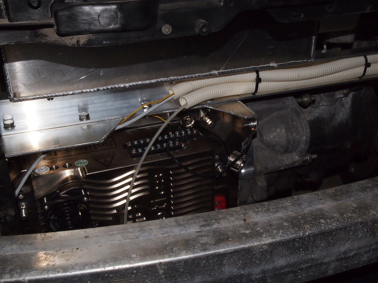
This weekend was all about cables. I mounted the DC/DC on the front battery box and connected it to the hight voltage in the front connection box, the engine room earth point, and the 12V "intake" in the left footwell under the driver's feet.

The DC/DC mounted on the front battery box with the orange high voltage cable
 
Originally, the 12V battery was placed in the rear of the car and two long cables ran to the front. One 50 mm2 cable to the starter and one thinner, 25 mm2 for the main power supply of the car. I ripped out those cables and joined them together. The starter end of the cable connects to the DC/DC so this way I get 12V for all the systems. Left to do is to connect a 12V battery to the DC/DC.
The two thick plus cables ripped out to be joined
 
Reducing the 50 mm2 cable to 25 mm2...

... in order to join it with the thinner with a crimp join. Add three layers of heat shrink and some electric tape
 
I also finished the middle connection box that goes in the right footwell and contains the main 400A fuse, the current shunt for measuring battery current (discharge and charge), and the Tyco contactor that turns on the high voltage.

The middle connection box under the passengers feet

The connections go to the JLD 404 to measure current and voltage, and to the charger to provide unbroken (by the Tyco) minus.

 
More orange tubes under the car...


... and the front connection box is filling up.
The front connection box is getting more and more complete. Left to connect are the hight voltage cables to the motor controller and the charger cable. I ran out of battery cable (a shielded, orange 35 mm2 cable) so I have ordered more from evpower.eu along with a charge intake and connector that conforms to the European standard IEC62196-2. Hope to get it next week.

September 21, 2014

A weekend with mostly head scratching

This weekend I was mostly scratching my head trying to figure out where to mount everything. There is not a lot of space in the tiny engine compartment of the Audi A2.
Anyway, I manage to squeeze in the box with the SSRs for the heating. It mounts on the front battery box, just next to the main brake cylinder. The original lid for the box will not fit so I will have to make a narrower lid from a piece of plastic. The SSRs are mouted on heatsinks that are glued to the connection box. It is the heatsinks that are bolted to the battery box so in fact the connection box is mounted to the SSRs and not the other way around.

The box with the heater SSRs just below the brake cylinder
Closeup of the SSRs

The Meanwell  DC/DC doesn't have any real mount points so I fabricated a mount by gluing on aluminum angle bars which will be bolted to the front of the battery box. I managed to glue it to the wrong side first but I realized that before the glue was dry ;)
According to its specs the glu has a shear strength of 12 N/mm2 so this mount, which is about 4 000 mm2, should withstand 48 kN. Since the DC/DC weighs about 3 kg, the mount will stand for 16 000 m/s2 or 1 600 g. I think it will hold!
 

Glue residue on top of the DC/DC

The stock Audi A2 150A battery fuse fits perfectly on the Meanwell.
The 150A fuse the used to be mounted directly on the 12V battery

I mounted some protective tubes for the cables to the motor controller. The top tube contains the brake lights cable (that turns the motor off if the brake pedal is pressed) and the ethernet cable to the controller. The bottom tube is yet to be filled with lots of stuff. I have ordered shielded cables to use for the throttle and tachometer so they won't. pick up noice from the controller.

The Soliton motor controller monted below the battery box and in front of the motor

I test mounted the front to see how much (little) space there is. There is some space to the right of the controller, in front of the transmission. There the charger will go. Note the red Sigg bottle to the left which is the vacuum container for the brake booster.

September 18, 2014

Front battery box and connection

Time for the front battery box that goes on top of the motor. Also here I had to compromise due to space limitations. Instead of having 3x8=24 cells it will have 3x7=21 cells. So the total of the car will be 2x22+21=65 cells. The total pack voltage will be 65x3.2=208 V instead of the 218 V that I first designed for. This will reduce the range with 5% (95 km instead if 100 km) and the maximum power with 10% (72 kW instead of 80 kW). I think it will be enough though, the max power of the gasoline engine was 55 kW! It will also reduce the power of the heater from 4.5 kW to 4 kW. This is more of a concern in our cold country!

The front battery box with insulation
The front battery box is mounted on two 30x50x4 mm aluminum U bars which in turn are mounted transversely on the front bars of the Audi frame. The frontmost bar is bolted to the frame using nut rivets and the rearmost bar is glued and riveted to the frame. This way the front bar can easily be removed in order to remove the motor and transmission.
The battery box is bolted to the U bars using nut rivets.
There will be a couple of components mounted on the battery box. Today I mounted the front connection box which holds a couple of connections bars and the fuse for the DC/DC and heater. On top of the connection box goes the Anderson power plug by which the battery can be disconnected from the motor controller and other systems.
The front battery box, the front connection box, and the red power plug
The + cable from the rearmost batterybox goes into the front battery box on the left and the resulting B+ from the whole pack goes out the other end (obscured) to the power plug.

September 17, 2014

Battery boxes

I had the battery boxes manufactures by IB Svets in UmeĆ„. This is a small welding company specialized in aluminum welding. The boxes are made of 3 mm aluminum which makes them very sturdy.
I will glu and rivet the boxes to the frame. This way I will not compromize the frame by welding, and the combined glue and riveting will hold for accelerations of 44 g vertical and 210 g horizontal! This is a factor 10 compared to the requirements. Of course the accelarations to accomodate for are not achived by the motor, but from braking and rolling the car in case of a crash.
The battery boxes are insulated with 10mm foam (camping mattress) to reduce the cooling in the winter.

First test mount of the rear battery boxes


The rear seats still fit!

And the trunk space is preserved

Time to grind the surfaces of the frame where the boxes will be glued


The boxes with insulation, connections and battery cells


The battery cables are kept in protective tubes. These are ordinary construction tubes painted orange.

The "drive shaft tunnel" has lots of space for the battery cables. The short black tubes are heat shrink that will eventually cover the cable glands

September 16, 2014

Space for the rear battery boxes

The most exiting thng that happened this summer was building the battery boxes. First thing to do was to cut holes in the car under the rear seat and trunk.


The holes for the rear battery boxes. Note the frame bar above the rear axle. 

Here it can be seen that the frame bar and the rear axle are not aligned on top of eachother.

The A2 is built using a technique calles Audi Space Frame. It means that there is a frame of aluminum tubes that supports the load rather than a monocoque that is the common way to build cars.

The Audi A2 Space Frame

The Audi Space Frame technology has been used for the Audi A8, R8, TT and the little A2. The advantage with the space frame is that the body panels do not take any load and it is possible to remove them without severely affecting the structural integrity of the car.

After making the holes I could measure for and design the battery boxes. It turned out that the rear axle and the frame bar are not aliged on top of eachother and this limits the front-to-back size of the box that is on front of the axle. I also realized that I need space for the connections to the side of the box so instead of having 12x2+5=29 cells the box will only accomodate 11x2=22 cells. My plans were to have 12+5=17 cells in the box behind the rear axle, but to compensate I made it the same size as the one in front of the axle. So, the net result is 44 cells instead of 46. This will shift the weight distribution of the car backwards, but I think I can live with that.

September 15, 2014

Parking brake

The conversion from drum brakes to disc brakes in the rear means I cannot use the same parking brake cables. After having studied lots of pictures of disc parking brakes last summer I thought I needed to custom build a cable and connection to the parking brake lever. This made med postpone the decision on how to do it.
This summer things suddenly looked better. I discovered that there apparently is a model of the A2 with disc brakes. I don't know if it has ever been sold in Sweden or elsewhere, but its parking brake cables are available as spare parts.
So after taking a chance on which cables to use I ordered them from the Audi dealer and I was able to mount the cables which fitted almost perfectly. I just had to trim the hand brake lever on the calipers with a drill so that the cable would fit.
I believe it was pure luck that the cables had the right length. The length is just right because of the angle at which I mounted the rear disc calipers. This was made just by looking at pictures of other cars!
The parking brakes work. But after driving the car without using the parking brake for half a year, it jams a bit. So I think a need to jog it back and forth for a while with some thin oil.
The parking brake cable connected to the lever on the brake caliper

Tank lid motor

I have designed a couple of safety features in order no avoid someone driving away with the car when it is connected to the charge cable.
  1. Starting the motor controller is only possible if the tank lid is closed
  2. It is only possible to open the tank lid if the ignition is off
For 1. I will have magnetic contacts the tell the controller if the lid is open or lcosed. For 2. I managed to integrate with the motor that opens the tank lid and disable it when ignition is on.

Connecting a relay on the cable that controls the tank lid motor

September 14, 2014

Integrating with ACC

I started off this summer with some electronics stuff. I managed to fry my Arduino computer last fall so I had to buld a new. This time with pre-built relay cards. Not messin with transistors and resistors on breadboards!
I am tapping in to the car in several different places to integrate with the existing systems. One such place is the ACC (Automatic Climate Control). The ACC has a temperature flap which opens when heat is demanded and closes otherwise. In order to have my electric heater only run when heat is demanded I want to sense the position of this temperature flap. Luckily the ACC also wants that so there is a potentiometer on the flap that the ACC reads in order to know the position of the flap. I found the cable that connects to the flap potentiometer on one of the connectors on th ACC control in the center dashboard.
The ACC control dismounted

The cable from the temp flap potentiometer


When full heat is demanded the output from the pot reads 0.6 V

When no heat is required about 4.7V is output (This was a warm day, around 28C so 22C means no heat)
 
I have removed the AC (Air Condition) pump fron the car. It was driven with a belt from the engine and in order for the AC to work I might need an electric pump. Anyway I am not sure it will fit in the engine compartment so maybe there will be no AC, only heat.

It's been a long winter...

... and I haven't really been doing much on the project. Too much work and a little lack of inspiration were the main reasons.
But with summer came summer leave, free time and lots of inspiration so the project is on again!
:)
The inspiration was not enough for both building and blogging so the build was prioritized!
But now, and will make some posts on the things I did this summer and the stuff I am working on now.