Showing posts with label Arduino. Show all posts

July 10, 2015

Emergency STOP and TP cable for display

I am using a small LCD display to show the status of the Arduino EVCU and up to now I have used a soldered wire between the Arduino and the display. That will not work when the Arduino and display are permanently mounted in the car so yesterday I replaced it with a standard TP (Twisted Pair) cable with RJ45 contacts which is normally used for Ethernet. The idea to use TP cable is so that I can have one cable installed in the car and another on the test bench. Installing the TP cable means soldering female RJ45 contacts to the Arduino and to the display. I will later change the display to a smaller (and blue) that will fit in the center console next to the JLD amp meter.
The display connected to the EVCU with a TP cable
The car needs to have an emergency stop button that breaks the high voltage circuit in case of an accident. Emergency stop buttons are usually large and ugly but I found a neat little button that fits the center console. When pressed, the button breaks the power to the Tyco contactor which then opens and shuts off the high voltage. Of course I managed to drill a hole in the console where it wouldn't fit :( so I'll have to find a new cover for that.
The pretty little STOP button and the TP cable for the display

June 28, 2013

Electric brake booster

While I am waiting for the really fun stuff to arrive, the motor, controller, adapter and batteries, I put together an electric brake booster for the car.
In a car with a diesel or gas engine, the engine produces vacuum which is used to boost the brake pressure so that you don't have to press the brake pedal so hard.
When I remove the enging there will be no more vacuum so I have replace that with something else.
So, I built a brake booster from a vacuum pump and vacuum sensor from an Audi A4, an old Sigg bottle that I used to have kerosene in for an outdoor stove, a contactor and the Arduino micro processor.
I use the Sigg bottle because it is red ;) and because it is aluminum. Since the car is made mostly from aluminum I want as much of the parts to be so as well.
The Arduino runs a very simple software the reads the pressure and turns the pump on and off between 600 and 800 mbar of vacuum.
The contactor, which is actually the security contactor that will be used to brake the high current circuit, will be replaced with  simpler 12V automotive relay.

Have a look at the video:

June 16, 2013

CAN Bus Analysis started

I managed to tap into the Drive Train CAN Bus today. The Audi has three CAN Busses. One for the motor, transmission, power steering and brakes basicly, the second for the air conditioning, windows and door and the third for the radio, navigation systems and so on. I need to understand the drive train bus in order to emulate an engine so that the ECU (Engine Control Unit) stays happy and, most important, so that the power steering works. The power steering turns itself off when there are no CAN Bus messages from the engine with the RPM.
I have been trying several times to access the CAN Bus through the diagnostics connector but it has been dead. Today I tried one of the contacts in the foot weell in the double floor on the driver side.
Success! It worked after I had also grounded the Arduino to the car body.
The driver side foot well with the Arduino with CAN Shield
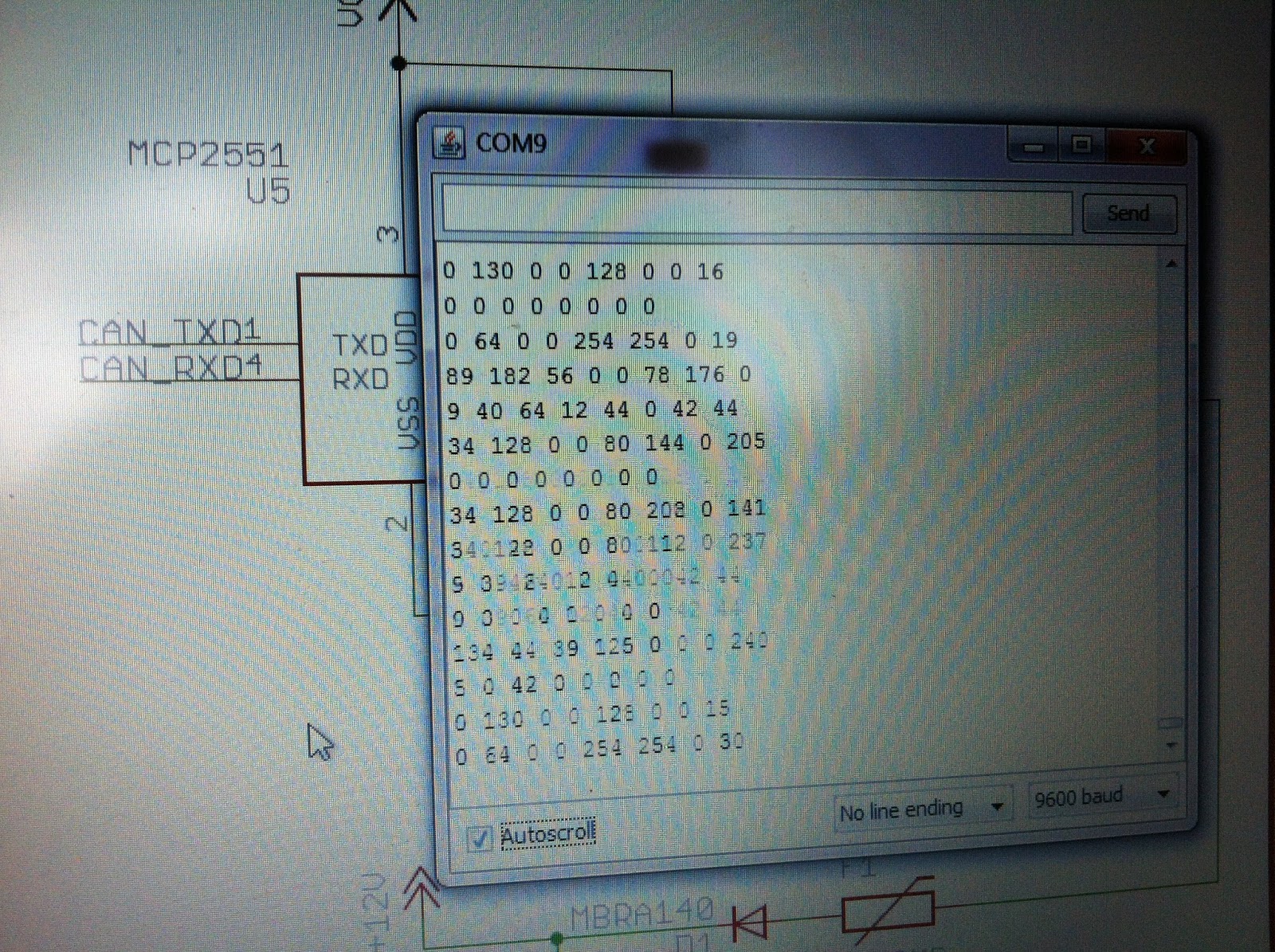
I managed to connect my home-built Arduino CAN Bus sniffer and get a lot of data out of it.
Now I only need to understand what all of it means ;)
Actually I managed to decode one CAN Message, Id 0x280 which is RPM (hooray= and I almost managed to work out which of the eight data fields are actually used. Well, I'll get back to that.